MMU
MMU
There are serveral different memory system architectures that exist for ARM architectures. One of those memory architectures is the protected memory system architecture, which is not used in our case. A virtual memory system architecture is built upon our four GB physical memory. This architecture needs a component called "Memory Management Unit" and tables containg memory regions and attributes for each region to manage the mapping between physical and virtual memory. How those tables are used and how the memory map looks like, are part of this chapter.
Funcionality
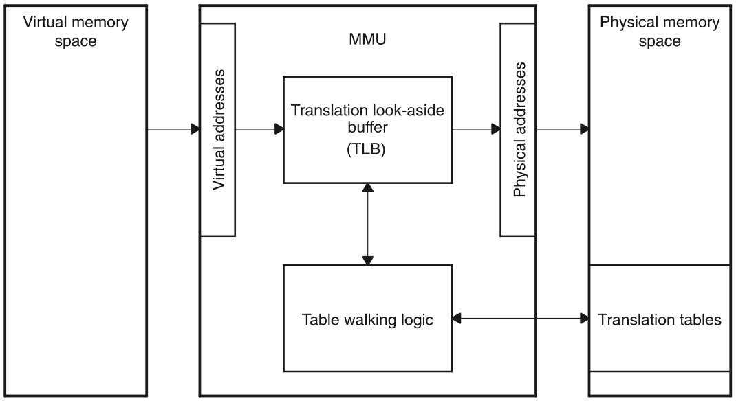
The system boots up with the MMU, which configures the virtual memory. The mapping between physical and virtual memory is handeled by the MMU. Virtual addresses can be directly mapped, but do not have to. Therefore the MMU needs information how to map addresses, the so called translation tables.
While the CPU is accessing a virtual address, the MMU has two supporting components, which are used to get the correct physical one. One is the "Translation look-aside buffer" short TLB, which is a cache of already translated addresses. This cache is of course limited and therefore cannot save all translations inside. If a translation of an address is already inside the TLB, the MMU can resolve the physical address immediately, otherwise it has to find the address via a table walk. How the table walk works is described in the "Translation Table" section.
The MMU has some advantages why it is actually used. Memory defragmentation and memory protection. Defragmentation is important to create contigous memory, therefore physical memory is translated into contigous virtual memory. Memory protection is important to actually control access of memory.
Translation Table(PageTable)
Translation table contain entries which have all the information included for translating a virtual address to a physical one and to resolve the type of memory accessing. There are different types of translation tables:
- First-level table (L1)
- Second-level table (L2)
- Third-level table (L3) available, but never used.
There can be different interpretations for L1 and L2 tables dependent on the configuration. One method describes the existance of only one L1 in the whole system containing one L2 for each process. Another one is the existance of one L1 for each process containg multiple L2 tables. We have chosen the second method, because a process can be significantly bigger than in the first method.
First-level table
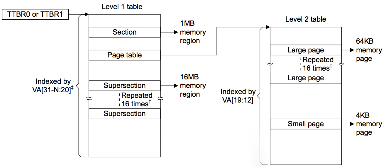
A first-level table consist of a maximum of 4096 entries each 4 bytes large. Depending on the format of the entry, it describes a section, supersection or a L2 table. Sections or supersections are normally used to describe big memory sections like the MMIO. Processes which can be seperated into smaller parts for a more efficient memory allocation and defragmentation, a L2 table is used.
| Entry type | Describes |
|---|---|
| Super Section | 16 MB memory region |
| Section | 1 MB memory region |
| Page Table | L2 table |
Second-level table
A second-level table consist of a maximum of 256 entries each 4 bytes large. Depending on the format of the entry, it describes a large or a small page.
| Entry type | Describes |
|---|---|
| Large Page | 64 KB memory page |
| Small Page | 4 KB memory page |
The reason why different sizes are available is a mixture of performance and space-saving. A 4 GB system built up only on small pages would lead to a 32 MB large translation table.
Both tables, the first and the second translation table have to be correctly aligned. A supersection and a large page are only multiples of the smaller types. If such types are used, the entries have to be repeated 16 times.
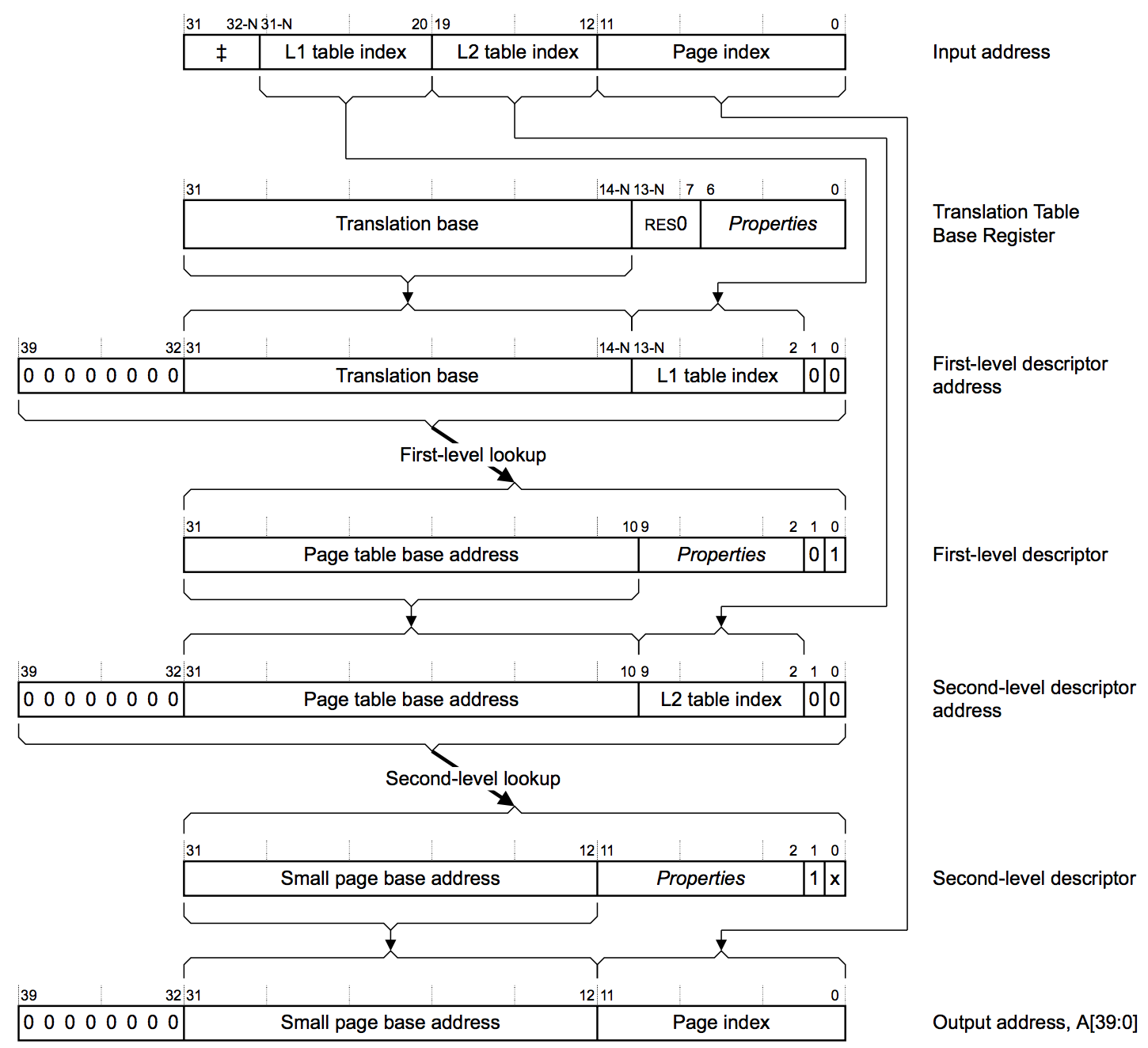
Table walk
A table walk is the procedure how a given virtual address is translated to a physical one. Depended on the type of the address accessed (sections or pages) different table walks are used. Following images show the translation walk for a section and a small page, which were used in this project.
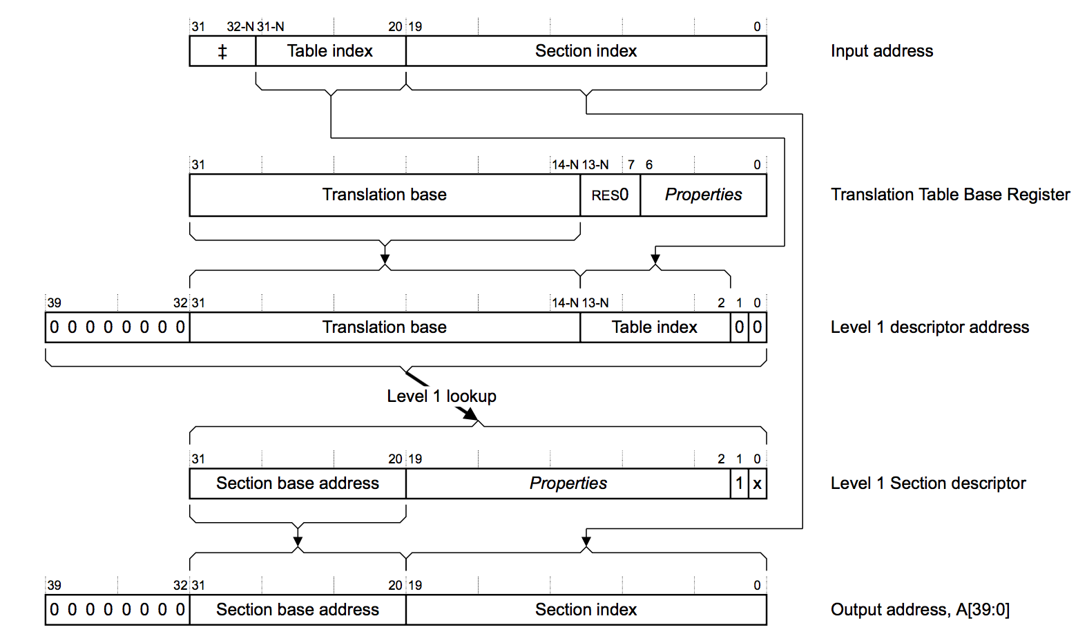
Descriptor Formats
As can be seen from the table walk, virtual addresses have different meanings of how they can be evaluated. If an address belongs to a small page, section, etc. depends on the descriptor format.
Next to the type of page it is, the actual base address, access permissons and caching/buffered status bits are part of the descriptor format.
/**
 * Table 3.2. First-level descriptor bits + address
 */
typedef struct {
    unsigned int type;                  ///< Page size and validity
    unsigned int CB;                    ///< Cached and buffered
    unsigned int domain;                ///< Domain control
    unsigned int AP;                    ///< Access permission
    uint32_t sectionAddress;            ///< Address of the section
} mmu_l1_section_t;

/**
 * Table 3.7. Second-level descriptor bits + address
 */
typedef struct {
    unsigned int type;                  ///< Page size and validity
    unsigned int CB;                    ///< Cached and buffered
    unsigned int AP;                    ///< Access permission
    uint32_t pageTableAddress;          ///< Address of page table
} mmu_l2_pageTable_t;
OS vs Process
The MMU offers a feature to explicitly differ between process and operating system space. Therefore the so called "Translation Table Base Register" short TTBR is used.
If the described feature is not used, the whole virtual memory has a reference to one running process. For example, a user process is currently running. It want to call a driver function, so the user process has to be swapped with the operating system. The TLB has to be flushed and the L1 or L2 (dependent on the configuration) has to swapped. To avoid this performance decrease, two translation tables are always loaded: the translation table of the operating system (TTBR1) is loaded once and the translation table of the process (TTBR0) is swapped, if the current running process is switched. Accessing the operating system do not lead in a switch now.
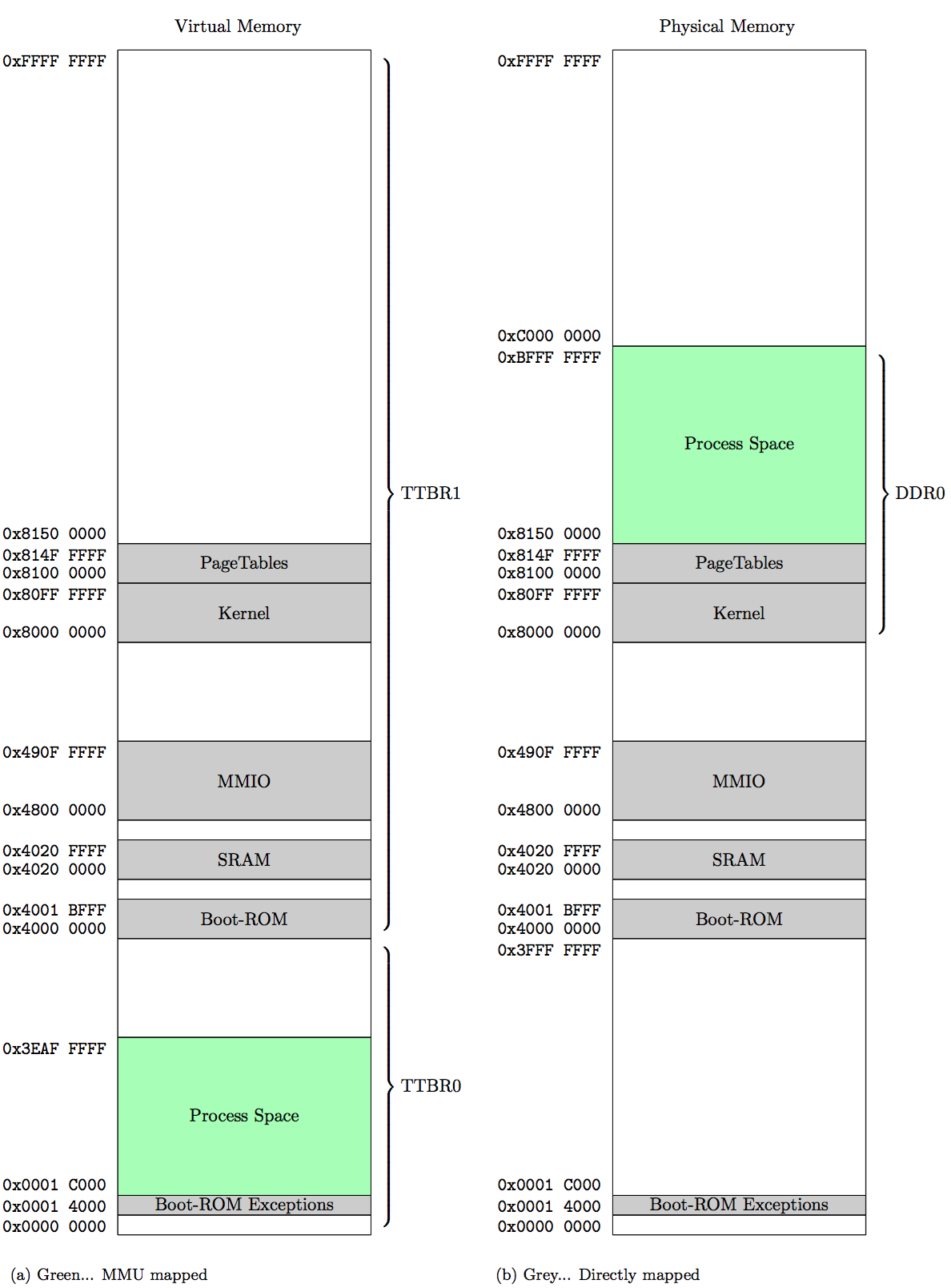
Memory Map
We used a virtual memory system architecture together with the seperation of OS and process. The process space (TTBR0 - 1 GB) is a quarter of the whole memory and only contain process specific information. The rest of the memory is used for the OS (TTBR1 - 3 GB) where next to our kernel implemenation and translation tables, all the hardware specific information is located.
| Memory Region | Size | Mapped |
|---|---|---|
| Process Space | ~1003 MB | Virtual mapped |
| Boot-ROM | ~2 MB | Directly mapped |
| SRAM | 64 KB | Directly mapped |
| MMIO | ~17 MB | Directly mapped |
| Kernel | ~16 MB | Directly mapped |
| Page Tables | ~5 MB | Directly mapped |
Hint: Each process consist of one L1 and greater equal than one L2 tables. For easier calculation each process has one L2. In a 5 MB region ~300 processes could have been space.
Implementation
First of all the whole MMU has to be initalized together with all the memory regions which are mapped directly. After this, the first L1 is created, containing all directly mapped memory regions. Afterwards all necessary settings like the size of OS and process have to be set.
void mmu_init(void)
{
    // initialize memory regions
    memoryManager_init();

    // disable mmu, to configure it
    mmu_disable();

    // create OS master page table
    // and has always a size of 16kB + alignment
    mmu_createMasterPageTable();

    // set ttbr1 and ttbr0 for
    // OS and Process page table
    mmu_setTTBR1(masterPageTable);
    mmu_setTTBR0(masterPageTable);

    // set boundary (size of ttbr1 and ttbr0)
    mmu_setTTBCR(BOUNDARY_QUARTER);

    // set domain
    // atm full access
    mmu_setDomain(0xFFFFFFFF);

    // enable MMU
    mmu_enable();
}
After the MMU is initalized, error handling and creating pages are close to each other. If a memory access occures and the address trying to access is not mapped yet, a data abort error is thrown. This error can be catched to get the error code. Dependent on the error code, a page table or a page entry can be created. After the creation, the interrupted process can continue.
void mmu_dabt_handler(void)
{
    // load dabt details via asm
    uint32_t dataFaultAddress = __mmu_load_dabt_addr();
    uint32_t dataFaultStatusRegister = __mmu_load_dabt_status();
    // Bit 10 + 3-0 for fault status
    // shift bit 10 to 4 to get one value
    unsigned int dataFaultStatus = ((dataFaultStatusRegister & 0x400) >> 6) | (dataFaultStatusRegister & 0xF);

    PCB_t* currentProcess = scheduler_getCurrentProcess();
    if (currentProcess == NULL) {
        return;
    }

    // check
    switch(dataFaultStatus) {
        case DABT_TRANS_SECTION_FAULT:
            // L2 needed
            mmu_createL2PageTable(dataFaultAddress, currentProcess);
            break;
        case DABT_TRANS_PAGE_FAULT:
            // Page frame needed
            mmu_createPageFrame(dataFaultAddress, mmu_getL2PageTable(dataFaultAddress, currentProcess->pageTable));
            break;
        default:
            // error cannot be handeled
            scheduler_killProcess(currentProcess->processID);
            break;
    }

    // go back to interrupt handler
}
Allocating page
If a page is already allocated or not is check based on a bitmap. To optimize this process, each byte can be checked at the beginning if one bit is free. If every bit is set to one, the next byte can be searched for free space.
Killing a proccess
After killing a process all the translation table entries and space of the process has to be cleared. No shared memory has been implemented, which simplifies the process of killing.
Work in progress
- ASID (Address space ID)
At the moment, after a process switch, the whole TLB is flushed. Using TTBR0 and TTBR1, the TLB contains entries of the OS and the current process. While switching the current process only the entries of the process in the TLB should be cleared, not all. ASID is a flag in the TLB, which is used to indicate which entry is associated to which process. Therefore only the process entries can be cleared which lead to a performance boost.
- Supersections&Large pages
For reasons of simplification, supersections and large pages are not yet implemented, because entries would have been repeated in the translation table.
- ROM-Exception vectors
Currently the ROM-Exception vector table is located in the user process space. It is important to secure this area, that no process can access and moreover abuse them.
- Max proccess count
An idea is to directly integrate a max count of processes with a max count of L2 tables for each process. The max count can be evaluated empirically or estimated. So for example each process can have five L2 tables:
x * ((1 L1 * 4096 Entries * 4 Byte) + (5 L2 * 256 Entries * 4 Byte)) <= 5 MB (PageTable RegionSize)
x = 213 // Max processes
- Null-Pointer
The address 0x0 has to be considered. If a call on this address takes place, the calling process should be killed.